Viscous damper series
FLUID VISCOUS DAMPER
1. Viscous damper (VFD)
As a part of the structural protection system, viscous dampers provide reverse viscous damping force during the relative motion of the structure. The damping force of viscous dampers comes from internal interactions within the structure, including:
① The interaction between damping medium and piston;
② The interaction between damping medium and oil cylinder;
③ The interaction between media;
④ The interaction between the piston rod and the seal.
This force, which is opposite to the speed direction of piston movement, is called damping force. During the operation of the damper, these interaction processes convert mechanical energy into thermal energy and dissipate it.
Jiangsu Gongbang Vibration Control Technology Co., Ltd. is committed to the technological development of the third-generation viscous fluid damper. Based on understanding and mastering the development of domestic and foreign product technology, and considering the process and heat dissipation, we have developed a new generation of viscous fluid damper product, a constant temperature viscous damper, and applied for an invention patent. The patent application number is ZL 2022 1 1404456.5, and the authorization announcement number is CN 115789158 B.
2. The third-generation viscous fluid damper can be defined as:
① Low viscosity methyl silicone oil is used as the medium;
② The hysteresis curve is full, and the energy dissipation mechanism satisfies the nonlinear N-S equation;
③ Efficient and long-life sealing system;
④ Low speed friction damping, less than 10% of rated load;
⑤ The product has a long lifespan, no oil leakage, stable performance, and can be used back and forth, taking into account both seismic and wind resistance.
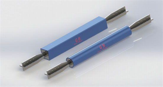
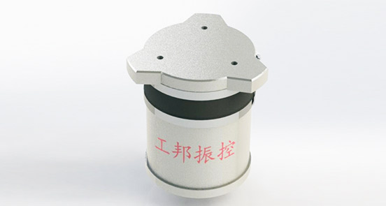
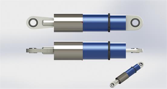
3. Appearance and geometric dimensions of dampers:

Table 1 External parameters of dampers:
序号 | 额定载荷(kN) | 销轴d(mm) | 外径D(mm) | 行程S(mm) | 销~销距L(mm) |
1 | 30 | 20 | 60 | ±600 | 根据客户安装要求,定制设计 |
2 | 60 | 25 | 83 | ||
3 | 100 | 35 | 102 | ||
4 | 160 | 40 | 127 | ||
5 | 250 | 50 | 152 | ||
6 | 400 | 60 | 194 | ||
7 | 650 | 80 | 245 | ||
8 | 1000 | 100 | 325 | ||
9 | 1800 | 140 | 402 | ||
10 | 2400 | 160 | 450 | ||
11 | 3000 | 180 | 500 | ||
12 | 3500 | 200 | 554 | ||
13 | 4000 | 220 | 610 |
4.选型参数
式中:F 为最大阻尼力、C为阻尼系数、V为设计速度、α为速度指数
F额定载荷(kN) | C阻尼系数(kN·(s/mm)α) | 速度指数 | V设计速度(mm/s) | 备注 |
200 | 70 | 0.15 | 1000 | 抗震 |
200 | 85 | 0.15 | 300 | 抗震 |
200 | 100 | 0.15 | 100 | 抗震 |
200 | 50 | 0.2 | 1000 | 抗震 |
200 | 65 | 0.2 | 300 | 抗震 |
200 | 80 | 0.2 | 100 | 抗震 |
200 | 25 | 0.3 | 1000 | 抗震 |
200 | 35 | 0.3 | 300 | 抗震 |
200 | 50 | 0.3 | 100 | 抗震 |
200 | 6 | 0.5 | 1000 | 抗震、抗风、桥梁 |
500 | 125 | 0.2 | 1000 | 抗震 |
500 | 160 | 0.2 | 300 | 抗震 |
500 | 200 | 0.2 | 100 | 抗震 |
500 | 65 | 0.3 | 1000 | 抗震 |
500 | 90 | 0.3 | 300 | 抗震 |
500 | 125 | 0.3 | 100 | 抗震 |
500 | 32 | 0.4 | 1000 | 抗震、抗风、桥梁 |
500 | 51 | 0.4 | 300 | 抗震、抗风、桥梁 |
500 | 80 | 0.4 | 100 | 抗震、抗风、桥梁 |
500 | 0.5 | 1 | 1000 | 抗震、抗风、桥梁 |
800 | 200 | 0.2 | 1000 | 抗震 |
800 | 255 | 0.2 | 300 | 抗震 |
800 | 320 | 0.2 | 100 | 抗震 |
800 | 100 | 0.3 | 1000 | 抗震 |
800 | 145 | 0.3 | 300 | 抗震 |
800 | 200 | 0.3 | 100 | 抗震 |
800 | 0.8 | 1 | 1000 | 抗震、抗风、桥梁 |
1000 | 250 | 0.2 | 1000 | 抗震 |
1000 | 320 | 0.2 | 300 | 抗震 |
1000 | 400 | 0.2 | 100 | 抗震 |
1000 | 125 | 0.3 | 1000 | 抗震 |
1000 | 180 | 0.3 | 300 | 抗震 |
1000 | 250 | 0.3 | 100 | 抗震 |
1000 | 63 | 0.4 | 1000 | 抗震、抗风、桥梁 |
1000 | 100 | 0.4 | 300 | 抗震、抗风、桥梁 |
1000 | 160 | 0.4 | 100 | 抗震、抗风、桥梁 |
1500 | 190 | 0.3 | 1000 | 抗震 |
1500 | 270 | 0.3 | 300 | 抗震 |
1500 | 375 | 0.3 | 100 | 抗震 |
1500 | 47 | 0.5 | 1000 | 抗震、抗风、桥梁 |
1500 | 87 | 0.5 | 300 | 抗震、抗风、桥梁 |
1500 | 150 | 0.5 | 100 | 抗震、抗风、桥梁 |
1500 | 1.5 | 1 | 1000 | 抗震、抗风、桥梁 |
2000 | 250 | 0.3 | 1000 | 抗震 |
2000 | 360 | 0.3 | 300 | 抗震 |
2000 | 500 | 0.3 | 100 | 抗震 |
2000 | 127 | 0.4 | 1000 | 抗震、抗风、桥梁 |
2000 | 205 | 0.4 | 300 | 抗震、抗风、桥梁 |
2000 | 315 | 0.4 | 100 | 抗震、抗风、桥梁 |
2000 | 63 | 0.5 | 1000 | 抗震、抗风、桥梁 |
2000 | 2 | 1 | 1000 | 抗震、抗风、桥梁 |
2500 | 315 | 0.3 | 1000 | 抗震 |
2500 | 450 | 0.3 | 300 | 抗震 |
2500 | 630 | 0.3 | 100 | 抗震 |
2500 | 160 | 0.4 | 1000 | 抗震、抗风、桥梁 |
2500 | 255 | 0.4 | 300 | 抗震、抗风、桥梁 |
2500 | 396 | 0.4 | 100 | 抗震、抗风、桥梁 |
2500 | 80 | 0.5 | 1000 | 抗震、抗风、桥梁 |
2500 | 145 | 0.5 | 300 | 抗震、抗风、桥梁 |
2500 | 250 | 0.5 | 100 | 抗震、抗风、桥梁 |
2500 | 2.5 | 1 | 1000 | 抗震、抗风、桥梁 |
3000 | 750 | 0.2 | 1000 | 抗震 |
3000 | 960 | 0.2 | 300 | 抗震 |
3000 | 1200 | 0.2 | 100 | 抗震 |
3000 | 380 | 0.3 | 1000 | 抗震 |
3000 | 540 | 0.3 | 300 | 抗震 |
3000 | 750 | 0.3 | 100 | 抗震 |
3000 | 95 | 0.5 | 1000 | 抗震、抗风、桥梁 |
3000 | 3 | 1 | 1000 | 抗震、抗风、桥梁 |
4000 | 505 | 0.3 | 1000 | 抗震 |
4000 | 720 | 0.3 | 300 | 抗震 |
4000 | 1005 | 0.3 | 100 | 抗震 |
4000 | 125 | 0.5 | 1000 | 抗震、抗风、桥梁 |
4000 | 4 | 1 | 1000 | 抗震、抗风、桥梁 |
5.典型性能曲线

本构关系(FV)

最大阻尼力滞回曲线

30圈疲劳性能测试曲线


频率相关性0.7f 1.0f 1.3f
6.建筑典型安装方式


无阻尼器建筑 阻尼器斜支撑 阻尼器人支撑


阻尼器横向支撑 阻尼器剪力墙 阻尼器套索式
7.桥梁典型安装方式


桥桩与桥梁用阻尼器 斜拉索用阻尼器
8. Factory acceptance
Viscous fluid dampers, in accordance with the requirements of "Building Energy Dissipation dampers" JG/T209-2012, third-party testing shall be conducted on 20% of different types of dampers, with no less than 2 sets, and 100% testing is required before leaving the factory. The detection content mainly includes:;
(1) Ultimate displacement (F-S);
(2) Regularity (F-V);
(3) Maximum damping force (F-S), if Party A has special requirements, the testing content can be added.
9. Shipping process
Before transportation, the shipping mark must be indicated on the packaging, which should indicate:
(1) Manufacturer's name, shipper, contact information and address;
(2) Product name, specifications, models, and quantity;
(3) Total number of boxes (pieces) and box number, bundle number;
(4) Receiving unit, contact person, contact information and address;
(5) Rainproof, moisture-proof, and handle with care markings, and add lifting signs if necessary.
Note: The above markings should be written in black with a neat and clear pen on the front or side of the wooden box.
10. Construction of viscous fluid dampers
The construction of viscous fluid dampers should comply with the relevant provisions of the current national standards "Technical Specification for Safety of High Altitude Operation in Construction" JGJ80-2016 and "Technical Specification for Safety of Construction Machinery Use" GJG33-2012. Combined with the construction and installation characteristics of viscous fluid dampers, safety measures should be formulated in the construction organization.
11. Entry acceptance
When the viscous fluid damper enters the site for acceptance, it should have product completion data and factory inspection reports. The steel, welding materials, seals, fasteners, and coatings used in viscous fluid dampers should have a quality assurance certificate and comply with the design documents. The manufacturing unit of auxiliary support components such as supports or connectors should provide raw materials and product quality assurance certificates.
12. Installation time
In order to avoid accidental contact, collision, or welding spatter with nearby equipment and structures, the installation of dampers should be carried out after the completion of surrounding construction.
13. Installation steps
Before installation, first check whether the installation nodes, installation dimensions, node plates, pins, and dampers meet the requirements of the design drawings.
For lightweight dampers, the damper, node plate, and pin shaft should be connected together first, and the damper should be installed in place by adjusting the node plate and embedded parts to fit together, using bolts or welding; For dampers with larger mass, first connect the node plate to the embedded parts, use bolts or welding, and then insert the damper into the middle of the node plate and fix it with a pin shaft.
For those with a flange connection at one end, the flange end can be fixed first, and then the pin shaft hole can be fixed through the pin shaft.
14. Project Acceptance Software Acceptance (Data)
Software acceptance (documentation):
(1) Damper type inspection report;
(2) Enterprise related qualifications (business license, account opening permit, and three standard system, etc.);
(3) Relevant qualifications of construction personnel;
(4) Construction organization plan, etc.
Hardware acceptance (documentation):
(1) Factory inspection report of dampers;
(2) Third party testing report for viscous dampers;
(3) Weld inspection report;
(4) Project disclosure materials;
(5) Report on acceptance of dampers upon entry, installation acceptance report of dampers and support components, etc.
15. Inspection and later maintenance of viscous fluid dampers
The viscous dampers provided by our company are lifelong maintenance free products, in accordance with the requirements of JGJ297-2013 "Technical Regulations for Building Energy Dissipation and Vibration Reduction":
The inspection of viscous dampers can be divided into regular inspection and emergency inspection based on the inspection time or timing. According to the inspection method, it can also be divided into visual inspection and sampling inspection.
Viscous dampers should be regularly inspected based on their design service life and design document requirements. Under normal usage, visual inspection should be carried out after 10 years or during building maintenance; Sampling inspection should be carried out when the design service life is reached. Viscous dampers should undergo sampling inspection after encountering disasters such as earthquakes, strong winds, and fires.
When visually inspecting viscous dampers, the appearance, deformation, and other issues of the dampers, supports, and connecting components should be observed. During visual inspection, attention should be paid to observing the appearance, deformation, and other phenomena of the energy dissipator, and timely handling should be carried out, as shown in Table 2.
When sampling and testing viscous dampers, typical dampers in service should be selected from the structure, and their basic performance should be tested in situ or laboratory. The test content should reflect the possible changes in performance parameters of the dampers during use, and estimate whether they can reach the predetermined service life.
Table 2 Visual inspection content and maintenance methods of dampers
序号 | 目测内容 | 维护方法 |
1 | 粘滞阻尼器表面有介质泄露 | 更换消能器 |
2 | 粘滞阻尼器连接部位的螺栓出现松动,或焊缝有损伤 | 拧紧、补焊 |
3 | 粘滞阻尼器及附件表面出现污垢硬化结斑结块 | 及时清除 |
4 | 粘滞阻尼器及附件表面锈蚀或损伤,防腐或防火涂装层出现裂纹、起皮、剥落、老化等 | 清理、修补、重新涂装 |
5 | 粘滞阻尼器或附件产生弯曲、局部变形 | 更换消能器 |
6 | 粘滞阻尼器周围可能存在限制阻尼器正常工作的障碍物 | 及时清除 |